Recent Posts

Pages: 1 [2] 3 4 ... 10
11
SoilWatch 10 / Re: sleep mode for soil watch 10
« Last post by pinolec on June 13, 2020, 07:53:00 AM »
This is a good question.
In general, microcontrollers are not designed to deliver currents in the range of 20mA efficiently. Some microcontrollers are specified for less current. But even if the microcontroller can deliver 20mA, usually will suffer a voltage drop. In other words at 20mA there will be some voltage drop. Please see the voltage drop for 3V and 5V supply (from ATmega328P datasheet).


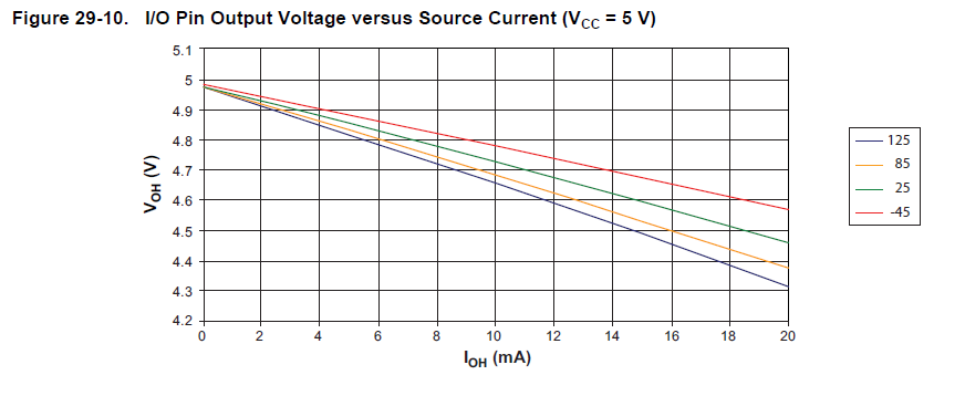
The voltage drop at worst 4.4V is still within the range of supply voltage of SoilWatch 10 sensor.


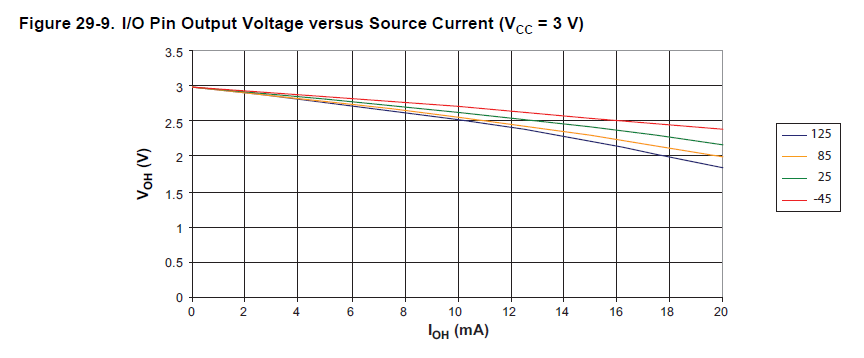
Now the voltage drop is below the specified voltage for SoilWatch 10. This will simply not work as expected.

This is the main reason we should use a transistor. With transistor, there will much less voltage drop.
12
SoilWatch 10 / Re: Soil Specific Calibration
« Last post by javierb on June 13, 2020, 04:05:19 AM »
Please Piotr, can you answer my questions?
I have 12 soilwatch 10 sensors (0-3v version)
This function is to obtain millivolts with the raw value from the pin analogRead.
   
    float mv_getValue(int raw){
    float mV = (raw * (1.1/1023.0))*1000;
    return mV;
    }

Perhaps this is my error, put 1,1 insted 3 or 3.3. The output of my sensors is 0 - 3 volts, and my board is arduino pro mini 3,3 v.
What number i must use 1.1, 3 or 3,3 ??

Regards
Javier
13
SoilWatch 10 / Re: Soil Specific Calibration
« Last post by javierb on June 09, 2020, 07:45:58 PM »
Hi Piotr!
Yes, i connect direct to the pin.
Why this is not recommended? Obviously before a set the pin as output.
Regards
14
SoilWatch 10 / Re: sleep mode for soil watch 10
« Last post by javierb on June 09, 2020, 07:31:08 PM »
Hi, what is the difference between connect the sensor thought transistor or direct to a digital pin and manage it with pinmode, digitalWrite and delay?
15
SoilWatch 10 / Re: sleep mode for soil watch 10
« Last post by pinolec on June 08, 2020, 09:56:40 AM »
It will work as long as you choose the transistor which works at 3.3V
Look for logic level MOSFETS with VGS threshold lower than 2V or best if the RDs(on) is specified for voltage 3.3V or lower.
I think I have mentioned somewhere on the forum example transistors which will work.

regards,
Piotr
16
SoilWatch 10 / Re: sleep mode for soil watch 10
« Last post by jeanpaullm on June 06, 2020, 06:15:19 AM »
Hi , I was wondering if the circuit that was posted above worked with 3.3V circuits


17
SoilWatch 10 / Re: Tasmota-Sonoff usage
« Last post by marcin_z on May 28, 2020, 08:36:01 PM »
Hi Piotr, thanks for the suggestion. Will do it in this way.
18
SoilWatch 10 / Re: Soil Specific Calibration
« Last post by pinolec on May 26, 2020, 07:14:24 AM »
Hi, can you help me with the sketch?
i am trying to obtain de VWC thought this function using milivolt as argument but i have very weird values, do you see something wrong with this part of the code?
I need to know 3 values of each lecture, raw, milivolts and VWC, and i call its separately and feed one with each other....

    int raw1 = raw_getValue(7, A1);
    float mVolt1 = mv_getValue(raw1);
    double vwc1 = vwc_getValue(mVolt1);

   
   int raw_getValue(uint8_t pinWrite, uint8_t pinRead) {
   int raw = 0;
   digitalWrite(pinWrite, HIGH);   // poner el Pin en HIGH
   delay(200);               // esperar...
   for (int i = 0; i < 3; i++) {
   raw += analogRead(pinRead);
   delay(200);  }
  digitalWrite(pinWrite, LOW);    // poner el Pin en LOW
  raw = raw/3;
  return raw;
  }

  float mv_getValue(int raw){
    float mV = (raw * (1.1/1023.0))*1000;
    return mV;
    }
 
  double vwc_getValue(float mv){
  float volt = mv/1000;
  double vwc = (5.5667*pow(volt, 3)) - (19.6738*pow(volt, 2)) + (31.0893*volt) - 6.7511;
  return vwc;
  }

Hi,

I can't see anything which may be wrong with the code at first glance. I do have some concerns.
Do you power the sensor straight from the pin? This will work for Arduino Uno but it is not recommended. To be able to power the sensor straight from the pin you need to set the pin as an output. Otherwise by default you just activating the pullup on this pin.
Code: [Select]
pinMode(7, OUTPUT);

What sort of outputs are you getting?

Kind regards,
Piotr
19
SoilWatch 10 / Re: Tasmota-Sonoff usage
« Last post by pinolec on May 25, 2020, 01:54:49 PM »
Hi,

As far as we know, without a hardware hack, Sonoff S20 will not work with our sensor.
Have a look at ESP8266 development modules. These modules work with ESPEasy and will probably work with Tasmota software. No hardware hacks are necessary.

Kind regards,
Piotr
20
SoilWatch 10 / Re: Soil Specific Calibration
« Last post by javierb on May 25, 2020, 04:55:51 AM »
Hi, can you help me with the sketch?
i am trying to obtain de VWC thought this function using milivolt as argument but i have very weird values, do you see something wrong with this part of the code?
I need to know 3 values of each lecture, raw, milivolts and VWC, and i call its separately and feed one with each other....

    int raw1 = raw_getValue(7, A1);
    float mVolt1 = mv_getValue(raw1);
    double vwc1 = vwc_getValue(mVolt1);

   
   int raw_getValue(uint8_t pinWrite, uint8_t pinRead) {
   int raw = 0;
   digitalWrite(pinWrite, HIGH);   // poner el Pin en HIGH
   delay(200);               // esperar...
   for (int i = 0; i < 3; i++) {
   raw += analogRead(pinRead);
   delay(200);  }
  digitalWrite(pinWrite, LOW);    // poner el Pin en LOW
  raw = raw/3;
  return raw;
  }

  float mv_getValue(int raw){
    float mV = (raw * (1.1/1023.0))*1000;
    return mV;
    }
 
  double vwc_getValue(float mv){
  float volt = mv/1000;
  double vwc = (5.5667*pow(volt, 3)) - (19.6738*pow(volt, 2)) + (31.0893*volt) - 6.7511;
  return vwc;
  }
Pages: 1 [2] 3 4 ... 10